No.333,jinyuan fourth road,jiangqiao town,jiading district,Shanghai
Tel:021-39556131
Fex:021-39556131
Email:info@senpu-sh.com
website:www.senpu-sh.com

No.333,jinyuan fourth road,jiangqiao town,jiading district,Shanghai
Tel:021-39556131
Fex:021-39556131
Email:info@senpu-sh.com
website:www.senpu-sh.com
Shanghai Senpu Electric Research Institute, Shanghai Sendi Voltage Regulation and Transformer Equipment Co., Ltd. Xu Kaiping Liu Qi
1 Introduction
The first induction voltage regulator in my country was designed in 1956 by He Mingguang, the leader of induction voltage regulators in my country, senior consultant and professor-level senior engineer of Shanghai Semper Electric Research Institute. In the following decades, through the painstaking research of Zhang Jingzhou, Liu Qi, Xu Kaiping and several senior engineers, the inheritors of the second generation of voltage regulators in my country and well-known experts on voltage regulators in China, they continued to develop, innovate and develop, and successively developed TDGA, TSGA type dry air-cooled TDA, TSA type oil-immersed self-cooling induction voltage regulator series products have laid a solid foundation for my country's voltage regulator business.
Since the establishment of Shanghai Semper Electric Research Institute, it has carried out all-round and optimized series design of induction voltage regulators. The new series of induction voltage regulators with different cooling methods and different purposes have been successfully trial-produced. These voltage regulators have been The majority of users use. Due to its excellent performance, reasonable structure, beautiful appearance and reliable use, the new series of induction voltage regulators are very popular among users.
The new series of induction voltage regulators successfully developed by Shanghai Semper Electric Research Institute are as follows.
a.TDA, TSA type oil-immersed self-cooling induction regulator;
b. TDFA, TSFA type dry air-cooled induction voltage regulator;
c. TYSA type oil-immersed self-cooling single-speed or third-speed induction voltage regulator for testing of voltage output motors and transformers;
d. TYSFA type induction voltage regulator for dry air-cooled motor and transformer test;
e.TGSA type induction regulator for oil-immersed self-cooling fertilizer industry.

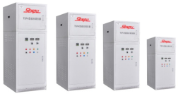
a oil immersion self-cooling

bDry air cooling
Figure 1 Outline drawing of induction voltage regulator
2 Product use
TDA, TSA oil-immersed self-cooling TDFA, TSFA dry air-cooled induction voltage regulators are successfully developed by Shanghai Senpu Electric Research Institute and Shanghai Sendi Voltage Regulation and Transformer Equipment Co., Ltd., and the product performance is the leading serialization in the country. product. This series of products can adjust the output voltage steplessly, smoothly and continuously under load conditions.
In order to meet the needs of no-load, load, locked-rotor, short-circuit and characteristic tests of motors and transformers, the company has also successfully developed high-voltage full-power, single-speed, double-speed, and third-speed voltage output. New series of presses.
The TDFA and TSFA dry-type air-cooled induction voltage regulators with output switch cabinet function are suitable for use in places where oil is prohibited, which not only saves the use of space, but also brings convenience to use.
The TGSA type induction voltage regulator for chemical fertilizer industry developed by our company is the most ideal temperature-controlling and voltage-regulating power supply for synthesis towers, alcoholization towers and alkylation towers in the chemical fertilizer industry.
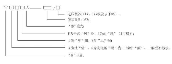
3 Model Specifications
3.1 Model

3.2 Product Specifications
For the specifications of general induction regulators, please refer to the "Product Center" of this website.
For the specifications of special purpose induction voltage regulators, please refer to the "Product Center" of this website.
4 Product performance
a. Small no-load current and low total loss;
b. Impedance voltage <10%;
c. The power frequency can be used for both 50 and 60 Hz;
d. The output voltage can be adjusted steplessly, smoothly and continuously;
e. The minimum no-load output voltage is not more than 5% of the rated output voltage, and the negative tolerance of the maximum output voltage is not more than 2% under the rated load;
f. Under the condition that the input voltage is symmetrical and the rated value, the asymmetry of the three-phase no-load maximum output voltage is not more than 1%;
g. When the input voltage is the rated value and the waveform distortion rate is not greater than 2%, the no-load output voltage (three-phase line voltage) is within the output voltage range above 25%, and the waveform distortion rate is not greater than 5%;
h. Sound level <85dB(A)
i. Overload capability

5 How it works
The electromagnetic structure of the induction voltage regulator is similar to that of the general vertical wound rotor asynchronous motor. It works in a locked-rotor state, and its working principle is similar to that of an induction motor and a transformer. When the relative positions of the stator and rotor are changed, the amplitude and direction of the induced potential of the secondary winding are changed for the single-phase voltage regulator, and the phase of the induced potential of the secondary winding is changed for the three-phase voltage regulator. Connection, the potential vector sum of the primary and secondary related windings and the output voltage can be adjusted steplessly, smoothly and continuously within a certain range.
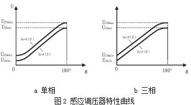
The output voltage characteristic curve of the induction voltage regulator is shown in Figure 2.

In the figure: U20=f(β), U2=f(β)——the output voltage characteristic curve at no-load and rated load respectively;
U20max, U2max——the maximum output voltage at no-load and rated load respectively, V;
U20min, U2min——the minimum output voltage at no-load and rated load, V;
β——The relative electrical angle angular displacement of stator and rotor, degrees.
6 Product Structure
The induction voltage regulator is mainly composed of the body, the transmission mechanism, the fuel tank (for oil-immersed products), the cabinet (for dry products), and the outlet device.
a. Body
The body is composed of a stator, a rotor, an upper cover and a base. In order to reduce magnetic flux leakage and prevent structural deformation, the upper cover, the base and the fuselage constituting the stator are made of cast iron. Three-phase stators and rotors are commonly used with double-layer short-distance stacked windings, and single-phase windings are commonly used with concentric windings.
b. Transmission mechanism
The transmission mechanism is composed of a secondary worm gear reducer, a limit device and a servo motor. The second-stage fan-shaped worm gear rotates the regulator rotor in the range of 180°through the guide plate.
The manual and electric switching is realized by the dog clutch. When the handwheel is pulled out, the claw clutch is disengaged, and the pressure can be adjusted by the handwheel; when the handwheel is pushed inward, the claw clutch is engaged again, and the electric pressure regulation can be realized.
The voltage regulator is equipped with electrical limit and mechanical limit. When the voltage regulator turns to the minimum or maximum value of the output voltage, the electrical limit is the limit switch action, which cuts off the power of the servo motor and stops the voltage regulator. , If the electrical limit fails, the fan-shaped worm gear will be disengaged from the large worm, and the mechanical limit will prevent the rotor of the regulator from rotating . The worm resumes meshing, so that the regulator enters the normal pressure regulation state.
The servo motor usually adopts a three-phase asynchronous motor. If the voltage regulation accuracy is high, a three-phase asynchronous motor with brake can be used. If it is automatic voltage regulation, a three-phase variable frequency motor (should be equipped with a frequency converter) can also be used.
A brass safety pin is installed between the fan-shaped worm gear and the guide plate. When the load is seriously overloaded or a short circuit occurs suddenly, the safety pin is cut off, and the fan-shaped worm gear and the guide plate are lost to ensure that the reducer will not be damaged.
c. Fuel tank
The small-capacity oil-immersed self-cooling induction pressure regulator adopts a corrugated oil tank, the medium-capacity product adopts a tubular oil tank, and the large-capacity product adopts a radiator-type oil tank. on the cover or panel of the press.
d. Cabinet
The body of the regulator is placed in the cabinet with the fan to form a dry air-cooled induction regulator.
The cabinet panel is equipped with digital display output voltmeter and output ammeter, and the three-phase output voltage and output current can be displayed respectively through the switch. The front door of the cabinet is also equipped with an air outlet temperature display device and an over-temperature sound and light alarm device. The user can make the voltage regulator realize step-up and step-down regulation through the boost and step-down buttons on the front door. The user can also switch the local control and remote control switch on the front door to achieve the opening and closing of the local control or remote control load, and the remote control device is configured by the user.
The fan adopts ST35 type two-way low-noise axial flow fan, which has the advantages of high efficiency and low noise.
e. Outlet device
The voltage regulator usually uses the standard type bushing outlet, and the low voltage and high current adopts the conductive outlet wire.
The input and output terminals of the oil-immersed self-cooling regulator are placed on the upper cover or panel of the regulator, and the input and output terminals of the dry-type air-cooled regulator are placed at the front and bottom of the cabinet. Type air-cooled voltage regulator, the input and output terminals are to be placed at the rear and front of the cabinet, respectively.
7 control lines
The voltage regulators have manual and electric voltage regulation functions. Manual voltage regulation is limited to assembly and commissioning. Electric can be divided into two kinds of control methods: jog pressure regulation and automatic pressure regulation.
Medium and small capacity oil-immersed self-cooling pressure regulators are generally equipped with simple pressure regulating controllers without output switches; large-capacity oil-immersed self-cooling pressure regulators can be configured with DVRS type digital pressure regulating control according to user requirements For details, please refer to the DVRS type digital voltage regulating control cabinet in the "Expert Forum" on this website.
The control part of the dry-type air-cooled voltage regulator and the main body of the regulator are assembled in the same cabinet, and the product has a compact structure and is easy to use.
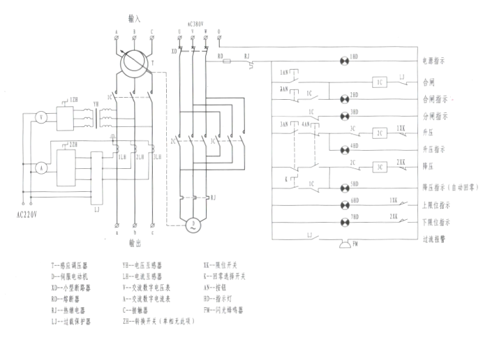
The commonly used voltage regulator control circuit is shown in Figure 3

Figure 3 Induction regulator control circuit (three-phase shown)
Press the button 1AN, the main circuit AC contactor 1C is closed, the closing indicator light is on, and the induction voltage regulator supplies power to the load.
Press the button 2AN, the AC contactor 1C of the main circuit is opened, the opening indicator light is on, and the load of the induction voltage regulator is powered off.
Press the button 3AN, the AC contactor 2C of the control circuit is pulled in, the boost indicator light is on, the output voltage of the induction voltage regulator rises to the required value, and the 3AN button stops jogging. If the jog button 3AN makes the output voltage rise to the maximum value, the upper limit switch will act, the servo motor will stop running, and the upper limit indicator will be on.
Press the button 4AN, the AC contactor 2C of the control circuit is pulled in, the step-down indicator light is on, the output voltage of the induction voltage regulator drops to the required value, and the 4AN button stops jogging. If the jog button 4AN reduces the output voltage to the minimum value, the lower limit switch acts, the servo motor stops running, and the lower limit indicator light is on.
Once the AC contactor 1C of the main circuit of the induction voltage regulator is opened, the control circuit will automatically adjust the output voltage of the voltage regulator to the minimum value (automatic zero return). non-return to zero" position.
Three-phase induction voltage regulator, respectively rotate 1ZH, 2ZH switch (single-phase without this switch), can display the real-time output voltage and output current of each phase of the induction voltage regulator through AC digital voltmeter and ammeter.
8 Installation, use and maintenance
8.1 Installation
a. Before installation, check that the rated capacity, rated input voltage, and output voltage range of the voltage regulator should be consistent with the actual voltage regulation requirements of the power supply voltage and load.
b. For newly installed or unused voltage regulators, use a 1000V (for products below 1kVA) or 2500V (for products above 1kVA) megger to measure the insulation resistance between windings to ground or between windings without electrical connection. , the insulation resistance value converted to the factory temperature of the voltage regulator, if it is less than 70% of the factory measured value, should be subjected to heat drying treatment. The treatment method is generally charged drying method or sent to drying room for drying. The conversion factor of insulation resistance to temperature is shown in the table below.
Insulation resistance conversion factor
|
Temperature difference (t2-t1)°C |
5 |
10 |
15 |
20 |
25 |
30 |
35 |
|
Conversion factor |
1.2 |
1.5 |
1.8 |
2.3 |
2.8 |
3.4 |
4.7 |
Note: In the table, t1 is the ambient temperature at the time of measurement, and t2 is the ambient temperature at the factory. When the temperature difference is negative, take the reciprocal of the data in the table.
c. There should be a space of more than 1m around the regulator to facilitate ventilation, heat dissipation and maintenance.
d. The regulator must be well grounded for personal and equipment safety.
e. The input terminal of the voltage regulator is connected to the power supply and the output terminal is connected to the load cable. The current density should be between 2 and 2.5A/mm2. The connection between the cable and the voltage regulator bushing or conductive bar should be safe and reliable. Good contact.
8.2 Use
8.2.1 Manual pressure regulation test
When the main circuit of the voltage regulator is not energized, pull out the handwheel of the voltage regulator and adjust it through the handwheel, so that the voltage regulator can be adjusted back and forth within the range of the upper and lower limits of the output voltage. Flexible rotation.
8.2.2 Electric control test
When the main circuit of the voltage regulator is not energized, push the handwheel of the voltage regulator inward to conduct the electric control test.
a. Check the direction of lifting and lowering
Press the up and down buttons to check that the steering of the servo motor should be in the same direction as that of the voltage regulator, otherwise any two input lines of the three-phase servo motor should be adjusted.
b. Limit switch action check
Jog the buck-boost button, artificially disconnect the normally closed contacts of the upper and lower limit switches, and check that the servo motor should stop rotating immediately. Otherwise, the two connecting wires of the contactor attracting coil to the upper and lower limit switches should be reversed.
c. Check the working state of the reducer
In the process of forward and reverse round-trip adjustment, the reducer should run smoothly without abnormal vibration and noise.
After the electric control test is over, the output voltage of the voltage regulator should be located in the middle of the upper and lower limit positions.
8.2.3 No-load voltage regulation
a. The input terminal of the voltage regulator is connected to the rated input voltage, and the output terminal is no-load. Check that the no-load output voltage range of the voltage regulator should be consistent with the nameplate output voltage range (the no-load maximum output voltage should be greater than the maximum nameplate output voltage)
b. After the no-load test, the no-load output voltage of the voltage regulator should be the minimum value.
8.2.4 Load voltage regulation
a. The input terminal of the voltage regulator is connected to the rated input voltage, and the output terminal is connected to the rated load.
b. When the voltage regulator is regulated with load, its output voltage must be gradually increased from the minimum value to the required value.
c. After each use of the regulator, the output voltage of the regulator should automatically return to the minimum value.
d. The output current of the voltage regulator should not exceed the rated value. Under special circumstances, the voltage regulator is allowed to be overloaded for a short time as specified.
8.3 Maintenance
a. In the state of power failure, regularly dedust and clean the voltage regulator.
b. For oil-immersed self-cooling regulators, the cooling oil should be filtered and dried regularly, and the cooling oil injected for supplementary injection should be of the same grade as the original cooling oil.
c. For dry-type air-cooled pressure regulators, check whether the fan works normally and stably. If any abnormality is found, the fan needs to be maintained or replaced with a new one.
d. The working conditions of the transmission mechanism should be checked frequently. If looseness or poor meshing are found, loosen the fastening bolts of the reducer and bearing seat, re-adjust the meshing degree of the worm gear and worm, reduce the axial play of the large worm, and then tighten the speed reducer. Adapter and bearing seat fastening bolts.
e. If the safety pin of the reducer is cut off due to severe overload or sudden short circuit of the load, the cause should be found out, the fault should be eliminated, and then a new H62 brass safety pin should be replaced.
f. Grease should be added regularly at the meshing parts of the worm gear, worm and bearings, and the oil cups and oil holes should be regularly filled with lubricating oil.
g. If it is found that the input and output terminals of the voltage regulator are loose, they should be tightened in time, otherwise the product will not work properly due to overheating caused by the contact resistance.
h. When the regulator is overhauled, the regulator body should be lifted out of the fuel tank or cabinet, the transmission device, panel and upper cover should be removed, the rotor should be lifted out, and finally the stator should be removed. When disassembling the stator and rotor, the lead wires of the stator and rotor windings should be marked to ensure that they are assembled and wired as they are after maintenance.